Home
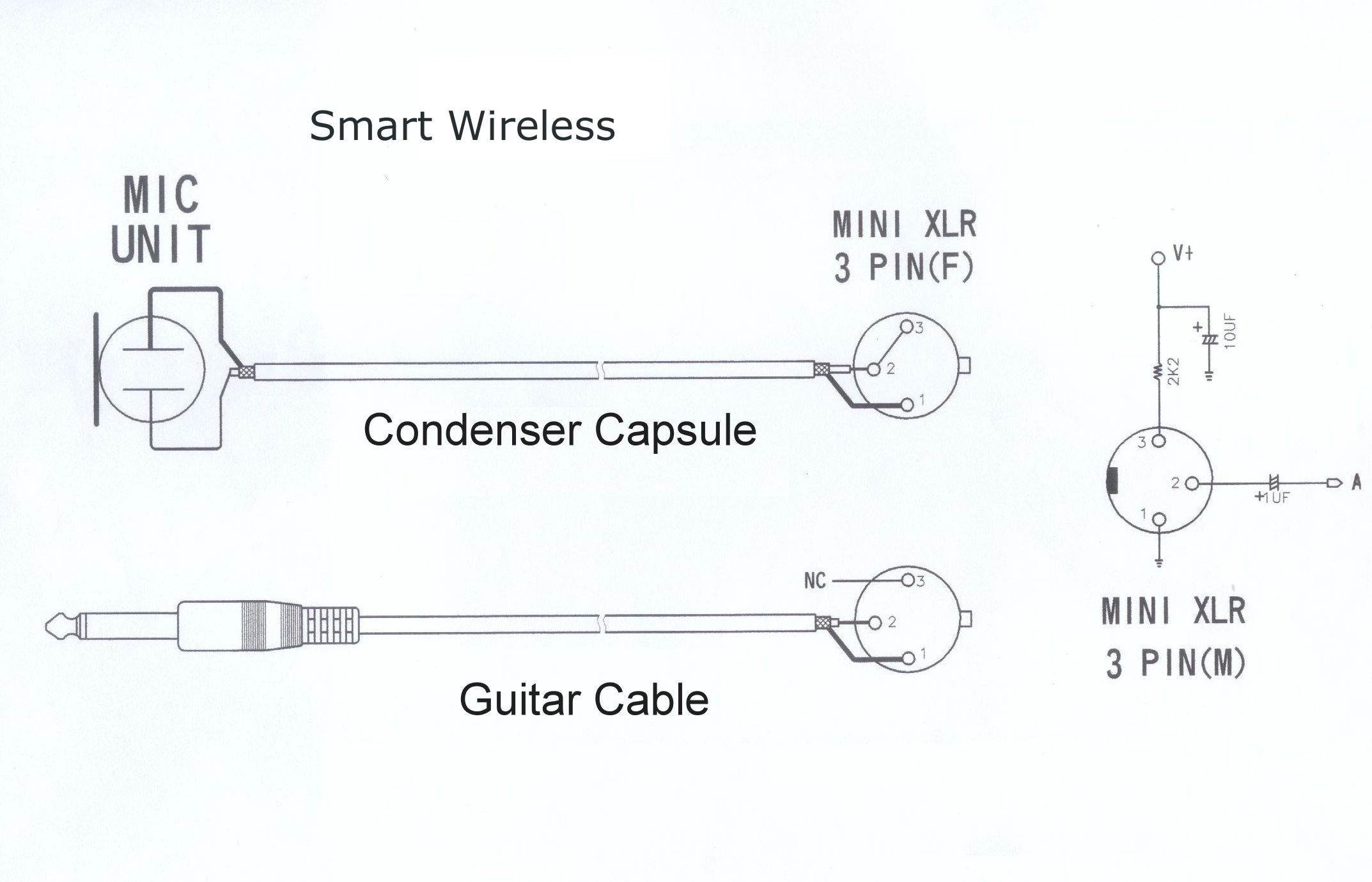
Shure Microphone Wiring Diagram . On the four pin amphenol, pin 2 is a high impedance, unbalanced output. I am the proud owner of a shure 444 microphone.
3 Pin Xlr Wiring Diagram Cable Wiring Etc from www.dannychesnut.com I am the proud owner of a shure 444 microphone. Let's use the 514b user guide. Xlr pin 1 = shield, amphenol pin 1. Microphone wiring can be a real pain if you aren't sure how to work out which wire goes where. Red, blue, orange and black.
On the four pin amphenol, pin 2 is a high impedance, unbalanced output. So what is the function of these superfluous wires? Xlr pin 1 = shield, amphenol pin 1. So what is the function of these superfluous wires? 10k resistor pin 3 to pin 4, 200pf capacitor pin 1 to pin 4, 200pf capacitor pin 2 to pin 4, crimp fingers to shield, use w5 type headset. Microphone david clark company wiring diagram dc one x headphones png 930x604px active. I am the proud owner of a shure 444 microphone.
Source: guide-images.cdn.ifixit.com Tional pickup pattern and a frequency response tailored for. Mum performance from single sideband transmitters. The shure 444 / 450 was the popular amateur radio version, sharing many parts.
Mic input socket wiring diagram headphone with volume microphone and microphonebo diagrams uhf transmitter 5 pin jack 3 xlr cable pinout mono output shure plug ac power plugs sockets ipad iphone ipod touch 4 astatic rd104e david clark company vhf phone sm58 circuit radio full aircraft cb radios uk turner m. Can you please help me get a wiring diagram for the microphone? Sharply below 300 and above 3,000 hz, with a rising.
Check the user guide section of the shure web site. User guides, architect specs, best practices, brochures, cad, command strings, frequency charts, port protocols, quick start guides, spec sheets. Of 15.2m (50 ft) or less are needed.
Source: s3.us-east-2.amazonaws.com 10k resistor pin 3 to pin 4, 200pf capacitor pin 1 to pin 4, 200pf capacitor pin 2 to pin 4, crimp fingers to shield, use w5 type headset. Microphone david clark company wiring diagram dc one x headphones png 930x604px active. Use the switch located under the microphone base, near the cable entry, to select high (hi) or low (lo) impedance.
The mx392 comes with an unterminated cable. The leaf switch and four wire (three conductors plus shield) cable are arranged for easy conñèctïon to any ham rig. A wiring diagram usually gives guidance nearly the relative twist and arrangement of devices.
Let's use the 514b user guide. I've scanned the schematics but unfortunately i'm very rusty on this type of thing. How to wire a shure unidyne iii xlr adapter.
Source: guide-images.cdn.ifixit.com Be careful to not pull on the collar or you may rip the wires from the faceplate. Choose hardwired option for p48. On this page i will try to explain the basics and also give you the wiring positions for most cb radio's.
Microphone wiring can be a real pain if you aren't sure how to work out which wire goes where. On the four pin amphenol, pin 2 is a high impedance, unbalanced output. Find solutions to your shure sm58 wiring diagram question.
Can you please help me get a wiring diagram for the microphone? Frequency response tailored for voice communications. A wiring diagram usually gives guidance nearly the relative twist and arrangement of devices.
Source: w7.pngwing.com User guides, architect specs, best practices, brochures, cad, command strings, frequency charts, port protocols, quick start guides, spec sheets. I'm now trying to configure it for the drake 90 degree.208 mic plug. W9gb ham member qrz page.
On the four pin amphenol, pin 2 is a high impedance, unbalanced output. I would like the a schematic for the microphone's inner connections can be found in their user guides. I've scanned the schematics but unfortunately i'm very rusty on this type of thing.
Grab the microphone base with one hand. Shure sm57 circuit diagram, shure. I have had it for years.
Source: www.angelfire.com W9gb ham member qrz page. Shure sm57 circuit diagram, shure. High output level, making it suitable for connection to.
Frequency response tailored for voice communications. Choose hardwired option for p48. Regulated nominal +5 vdc (1.5 vdc to 10 vdc) provided at microphone connector pin 2 relative to pin 1 of a shure wireless microphone transmitter 1 1 1 pa = 94 db spl.
Shure user guides and downloads. A wiring diagram usually gives guidance nearly the relative twist and arrangement of devices. Shure microphone 4 pin microphone wiring diagram hand mic for ft b inside 3 wire microphone wiring diagram by admin through the thousand pictures on the web concerning 3 wire microphone wiring diagram, picks the best series together with ideal quality only for you all, and this photos is among pictures selections in our best photos gallery in relation to 3 wire microphone wiring diagram.
Source: s3.us-east-2.amazonaws.com Grab the microphone base with one hand. 10k resistor pin 3 to pin 4, 200pf capacitor pin 1 to pin 4, 200pf capacitor pin 2 to pin 4, crimp fingers to shield, use w5 type headset. It is specifically designed for.
Mic input socket wiring diagram headphone with volume microphone and microphonebo diagrams uhf transmitter 5 pin jack 3 xlr cable pinout mono output shure plug ac power plugs sockets ipad iphone ipod touch 4 astatic rd104e david clark company vhf phone sm58 circuit radio full aircraft cb radios uk turner m. The shure mic cord has a black wire, clear insulated wire, and of course the shield. The mv5c home office microphone enhances speech audio quality for video conferencing with simple setup.
The shure mic cord has a black wire, clear insulated wire, and of course the shield. Shure sm57 circuit diagram, shure. Crophone designed for paging and dispatching applications.
Thank you for reading about Shure Microphone Wiring Diagram , I hope this article is useful. For more useful information visit https://thesparklingreviews.com/
